Open-source view camera
Calegari View 1
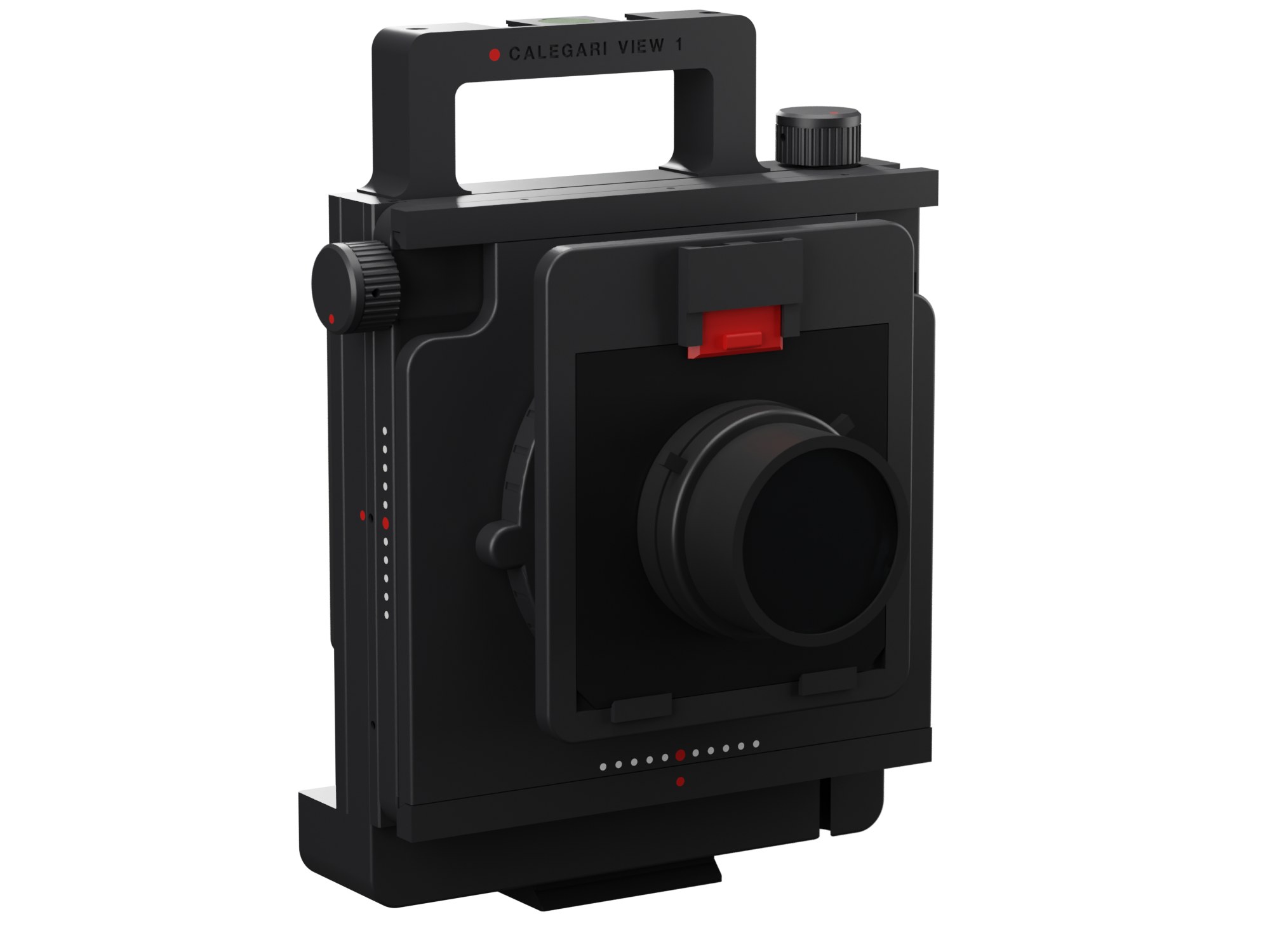
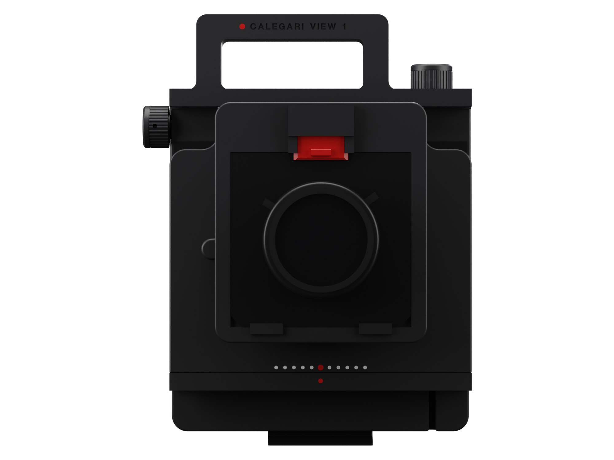
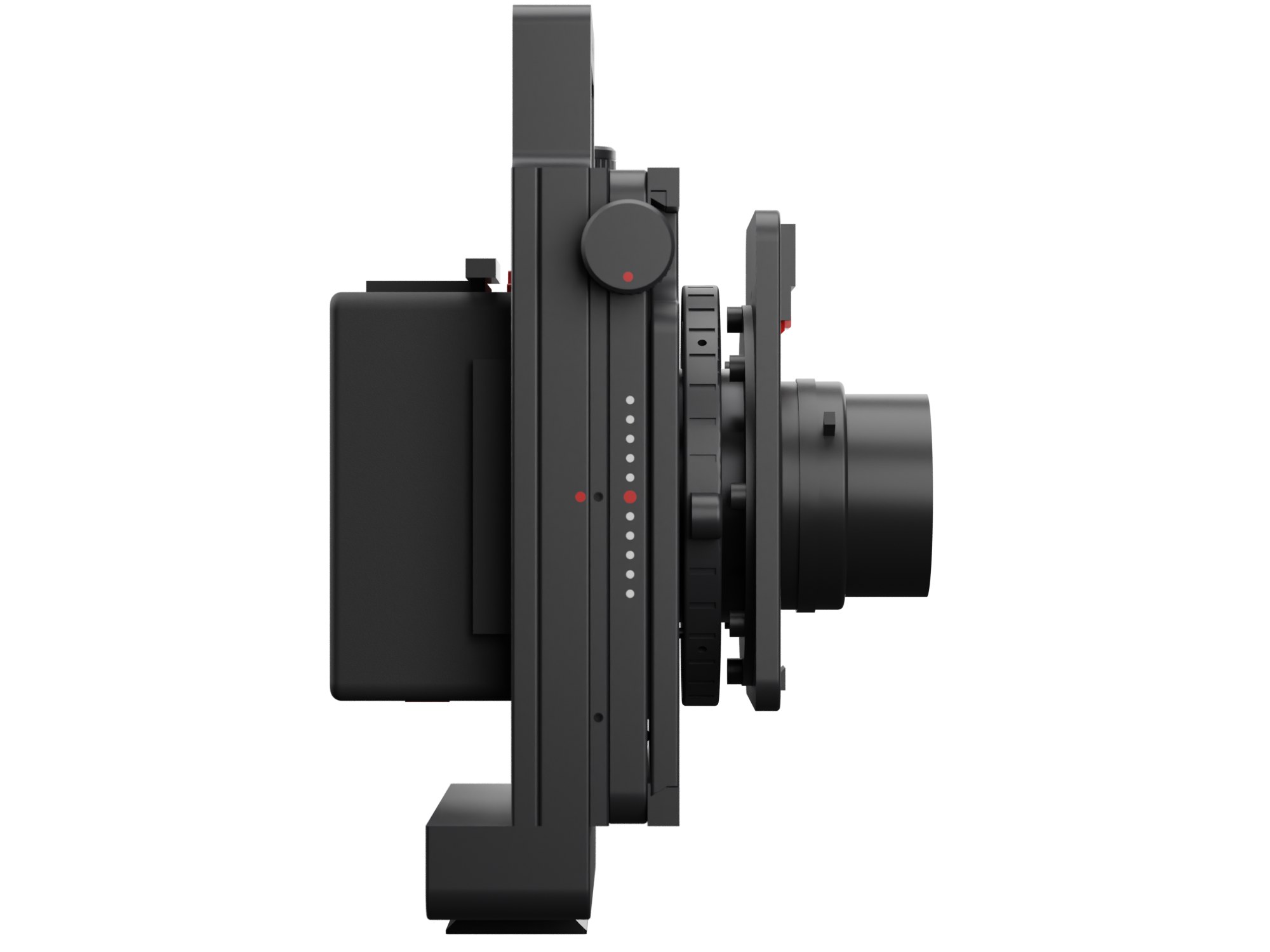
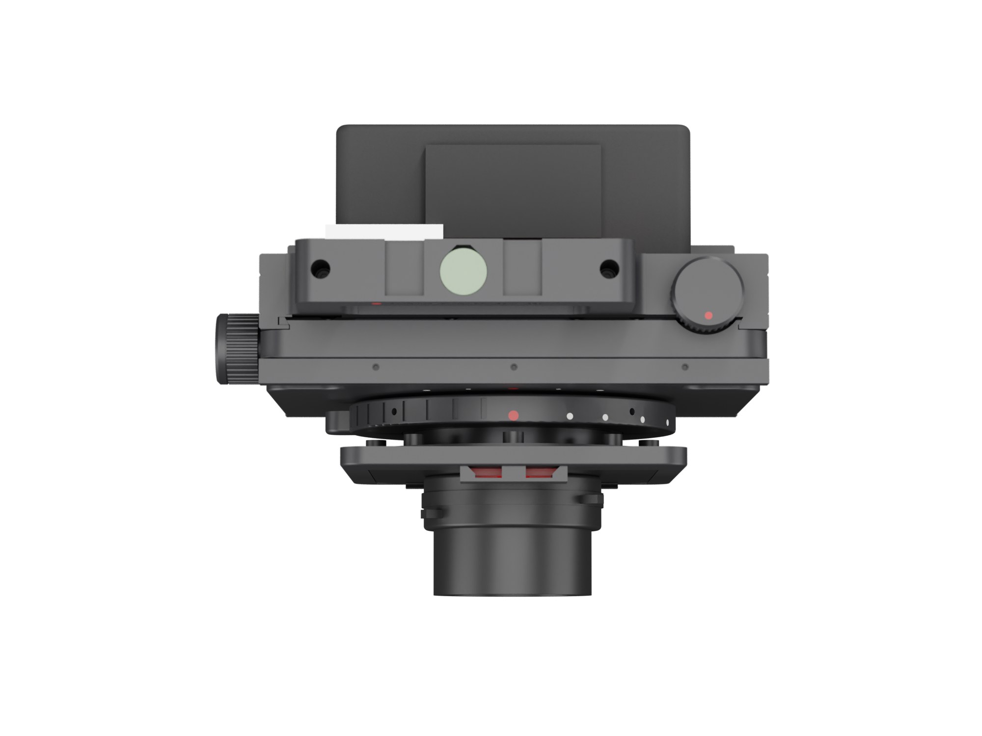
A rigid 6×7 architecture camera you print at home. Rise and shift on screws, focus on a helicoid, Mamiya RB67 backs, large-format wide angles.
Open-source view camera
A rigid 6×7 architecture camera you print at home. Rise and shift on screws, focus on a helicoid, Mamiya RB67 backs, large-format wide angles.
Why
I have wanted a view camera for years. The rigid kind, compact, built for architecture: you put it on the tripod, raise the lens a couple of centimetres and the verticals stay vertical, straight on the negative, with nothing to fix afterwards.
The problem is the price. A new Arca-Swiss or Silvestri costs thousands before you add a lens, and the used market is not much kinder. So I designed my own, around what I already had: a Bambu Lab P1S, the Mamiya RB67 backs you can find everywhere for little money, and a used large-format wide angle.
Everything is here: the print files, the parametric model they come from, the shopping list with links and step-by-step instructions. Without back and lens, the parts cost about 350 euro, much of it in packs of screws and inserts that will outlast the camera.
Specifications
Gallery
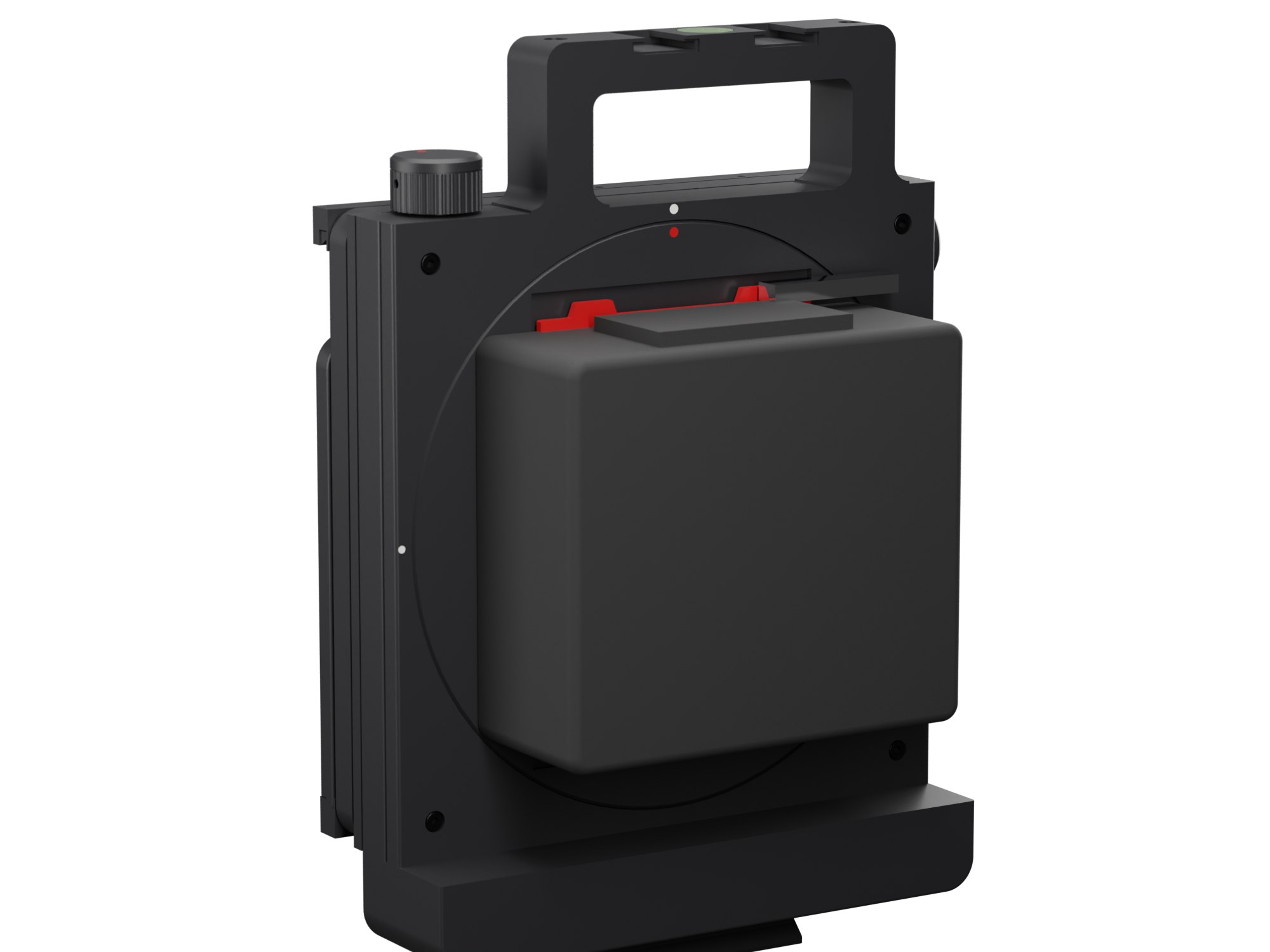
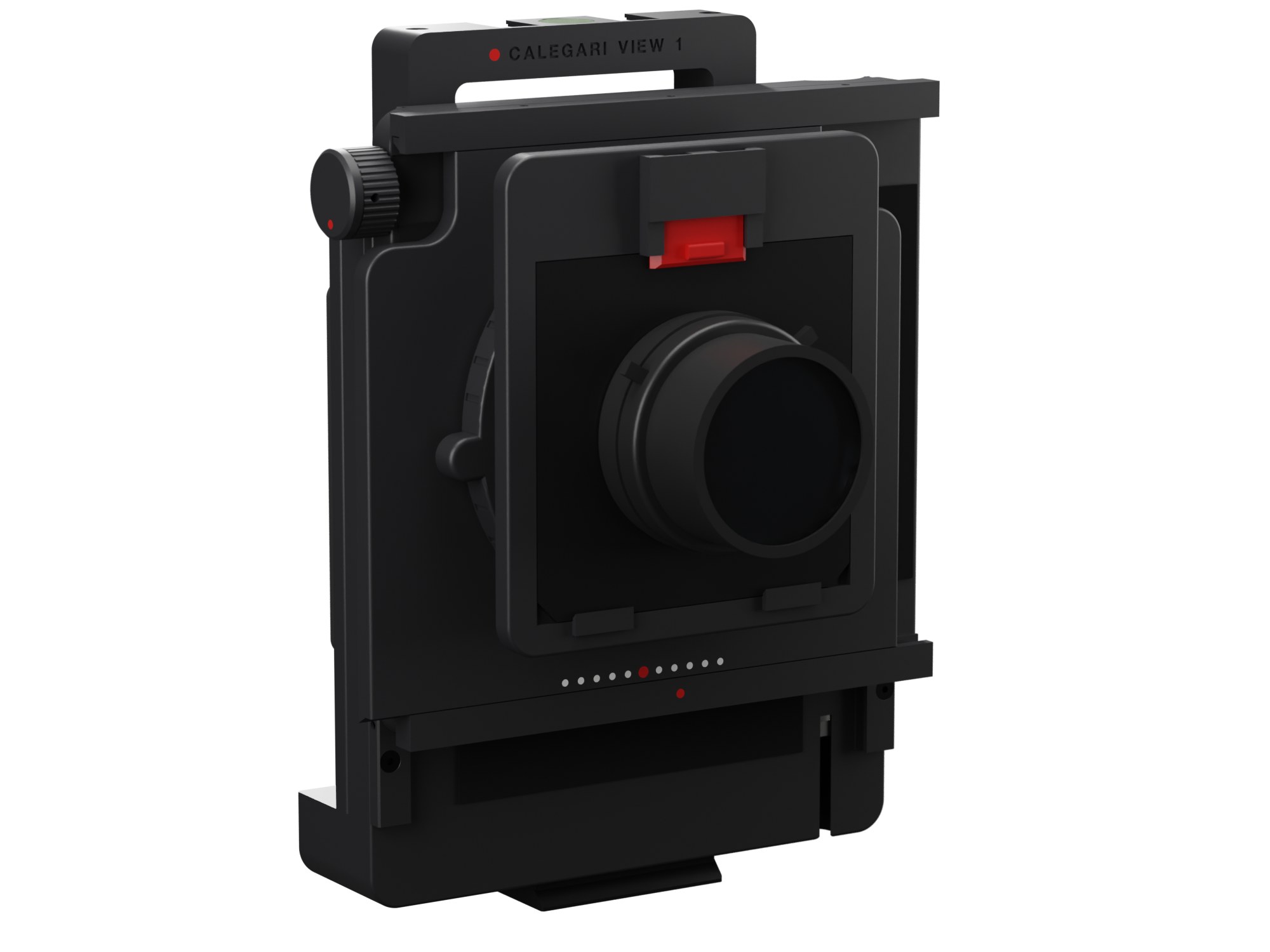
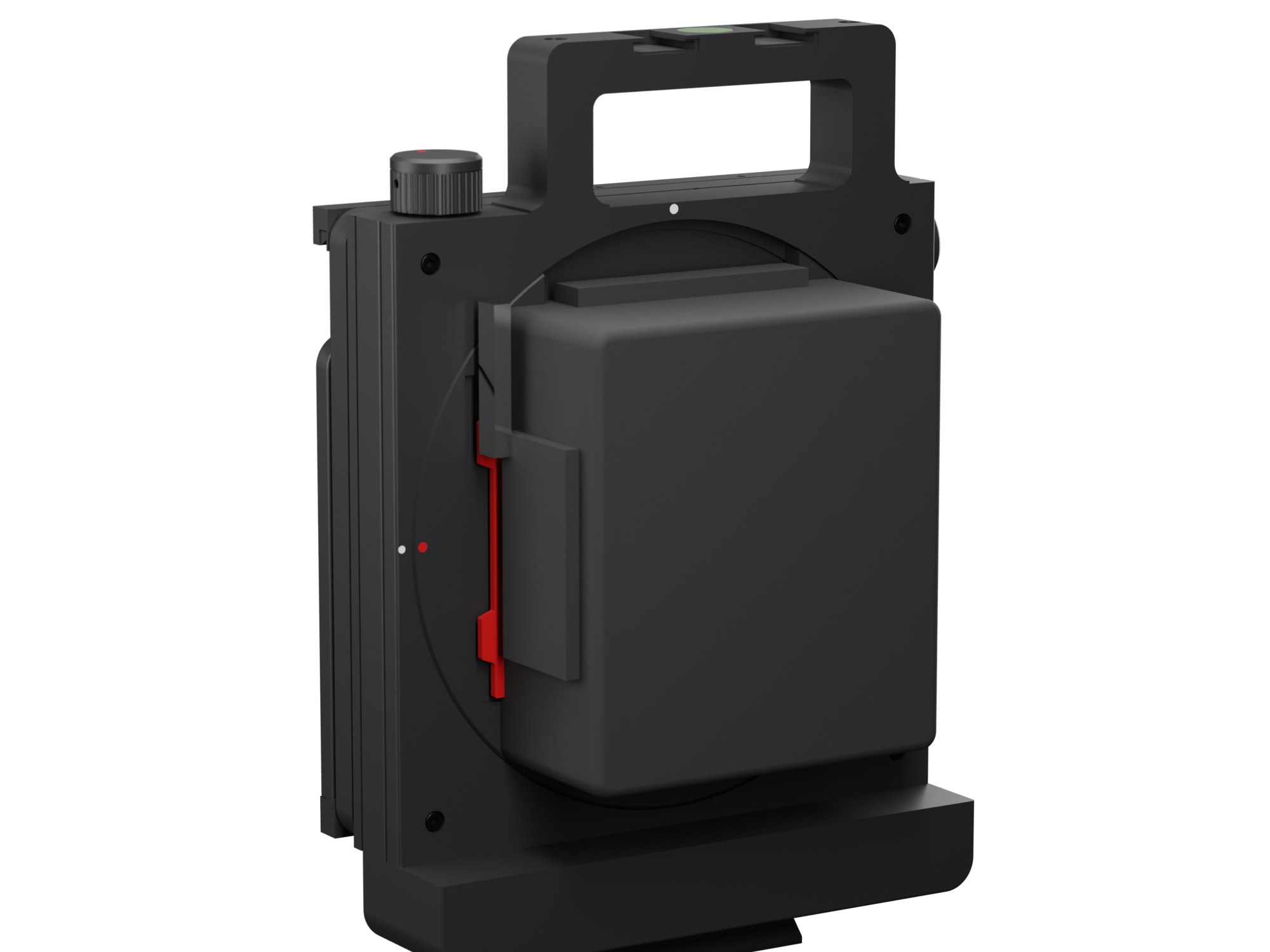
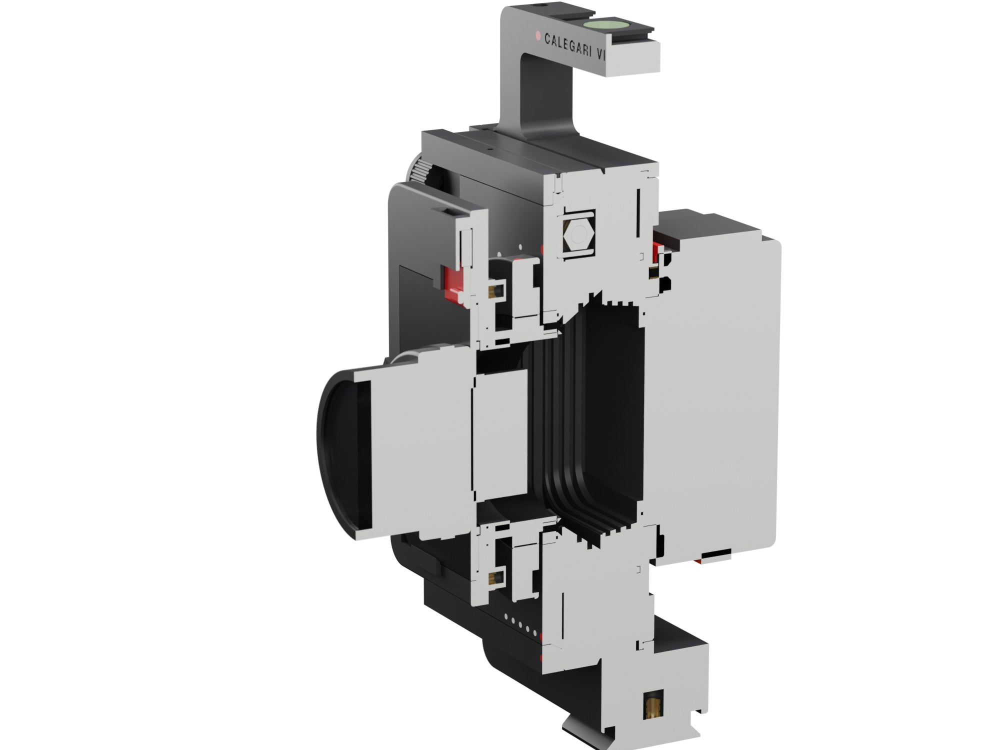
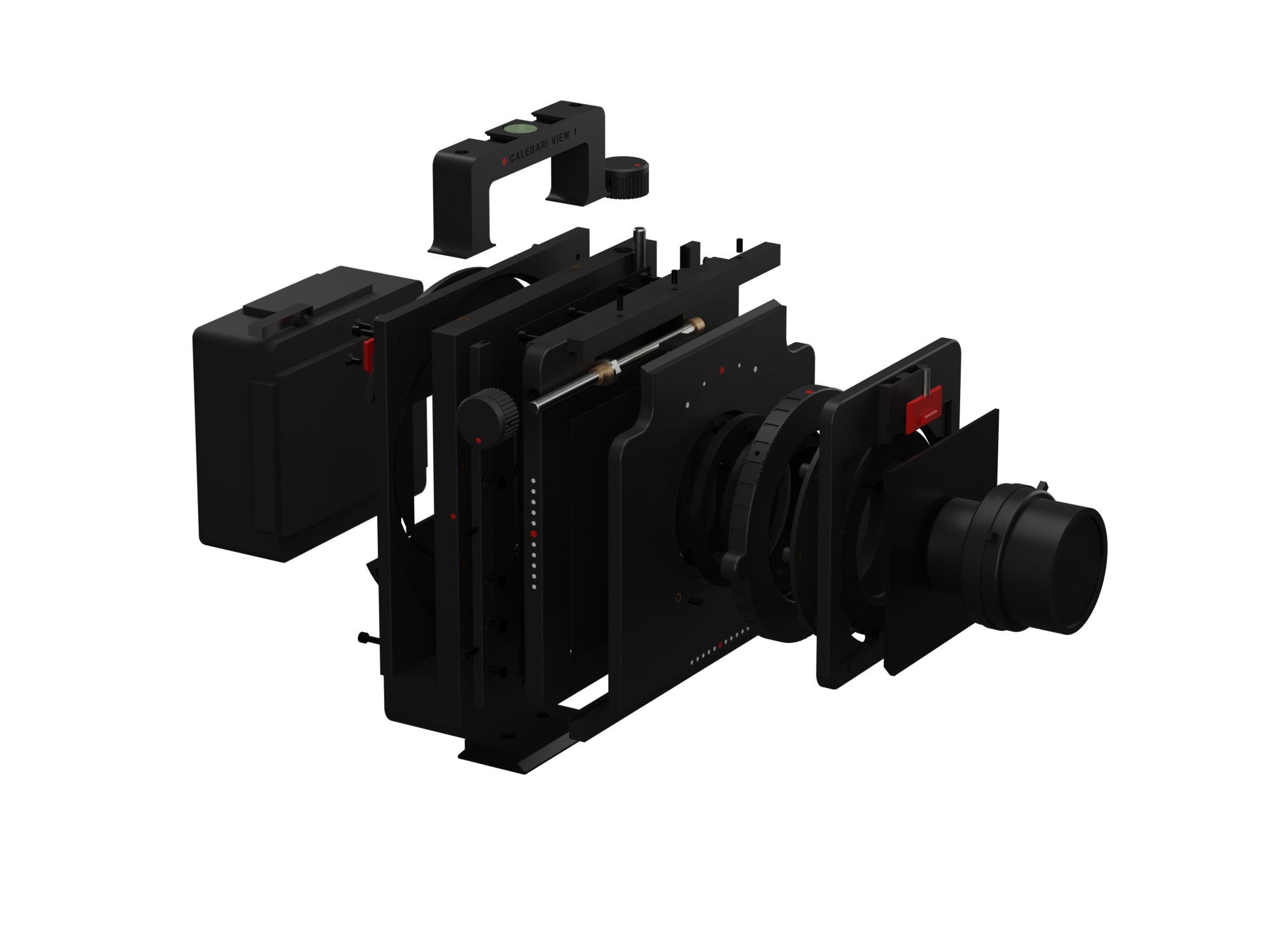
How it works
Build
Four hours of test prints first: the shrinkage of your ASA, the back interface, slices of the dovetail ways and the M65 thread. Then seven plates of black ASA and one of red. The guides assume you have never held a view camera: every step is split into short sub-steps, each picture shows only the new parts pulled out toward where they go, and a table says what goes where. The calibration guide is illustrated the same way. Every screw, insert and nut is listed with a link in the shopping list.
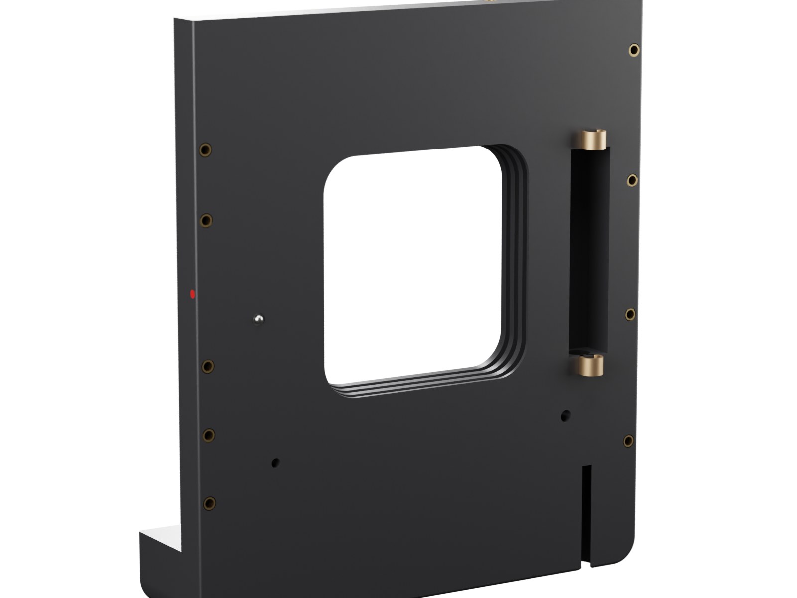
Heat-set inserts on four faces, the rise detent, two bushings.
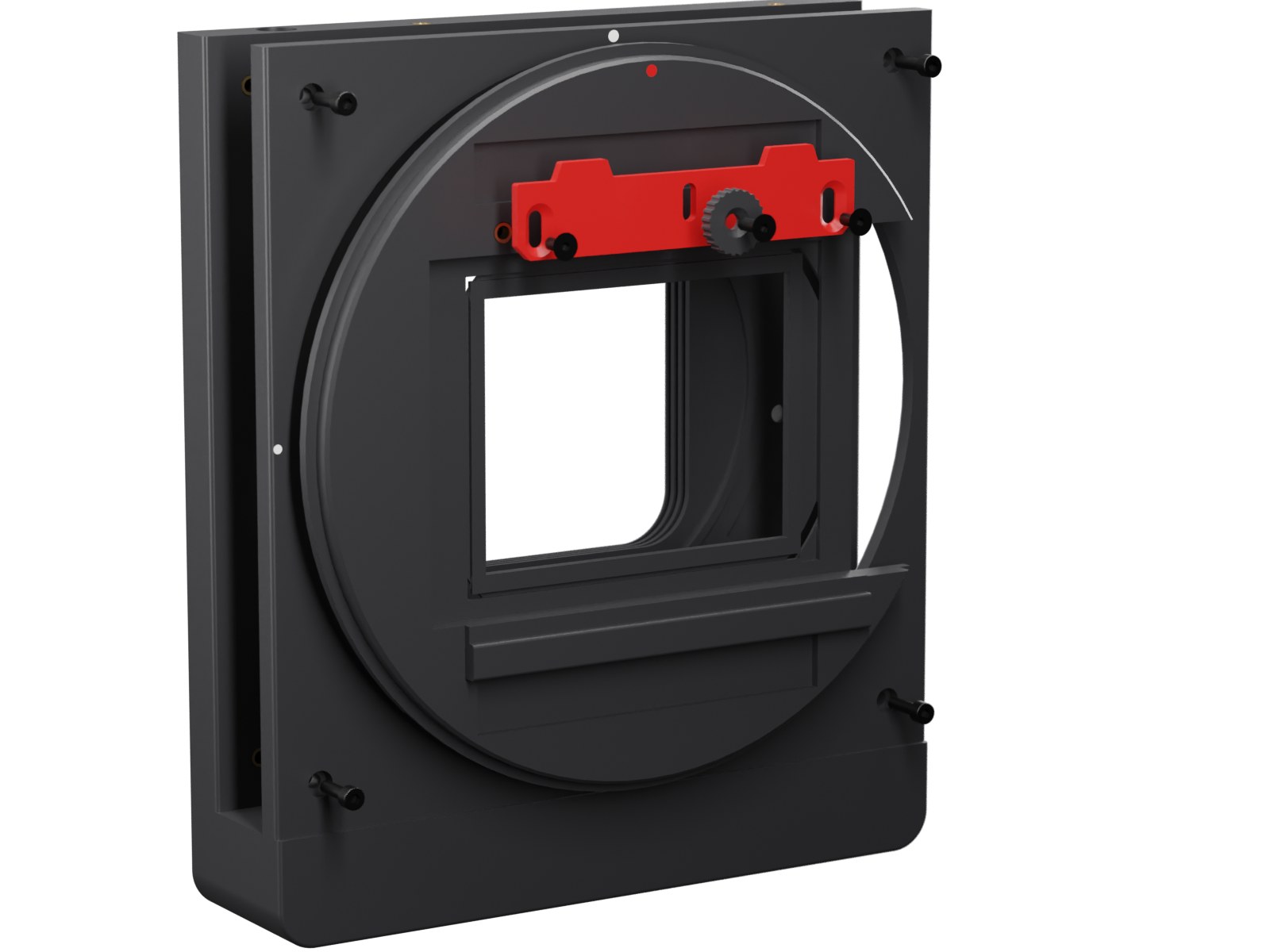
Red blade and wheel on the rotator, then the rotator, a velvet ring and the rear frame; a click and a stop from the front.
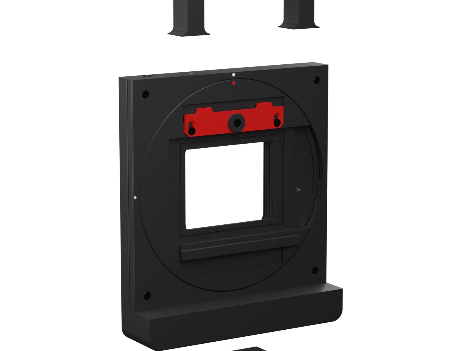
One aluminium plate underneath, the top handle, a bull's-eye level.
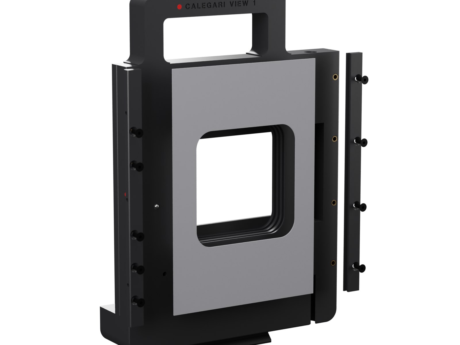
Two printed dovetail rails and the body velvet.
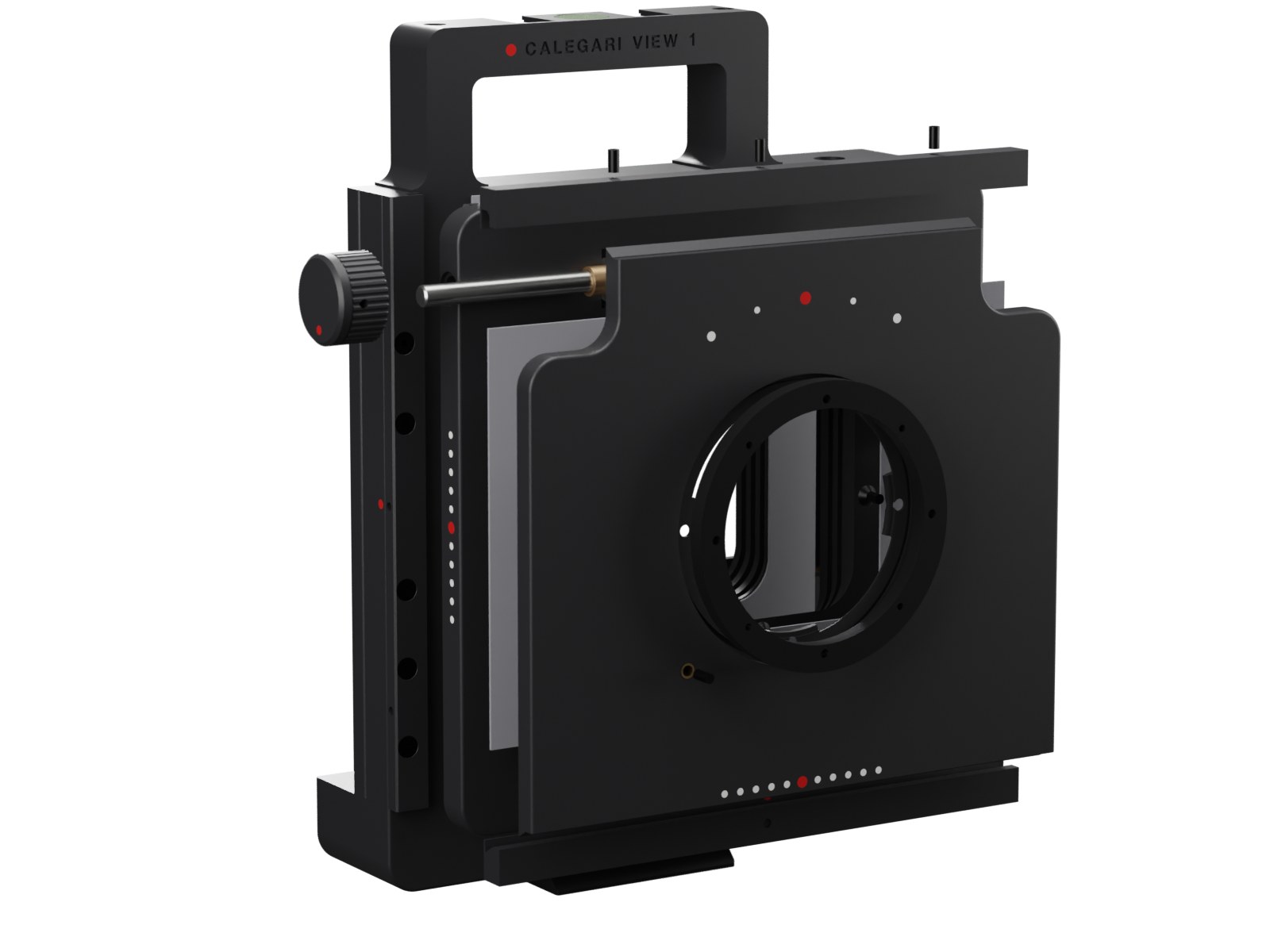
On the bench: Y plate, lens panel, horizontal ways, gib, shift screw and knob.
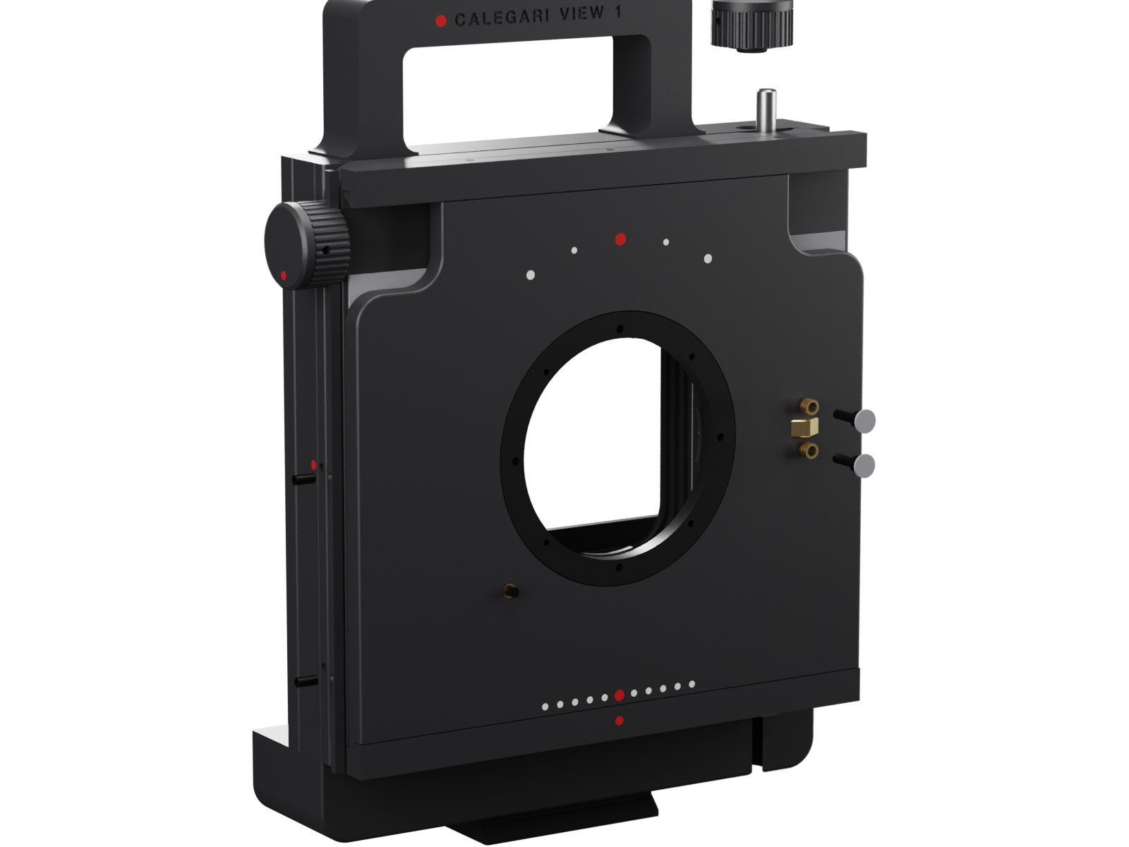
It slides in from the top; rise nut, rise screw and knob.
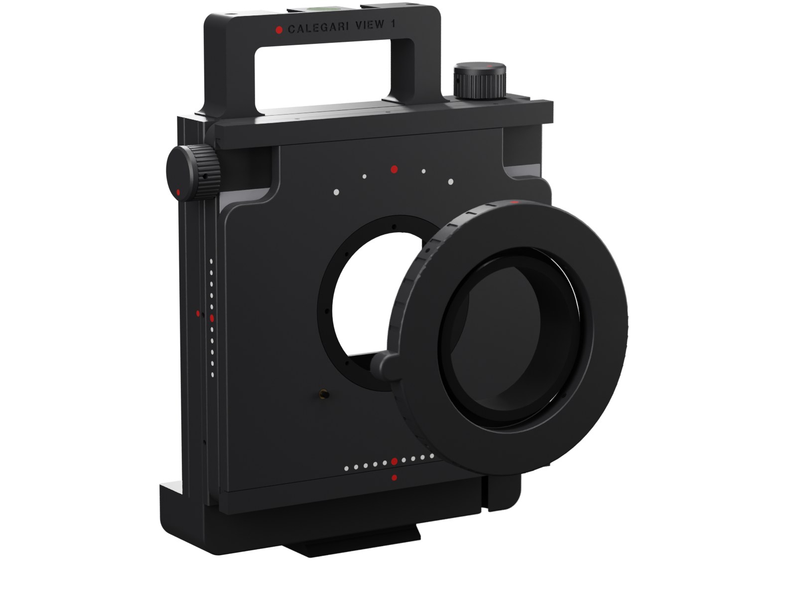
Set at calibration, with the red infinity dot on the index.
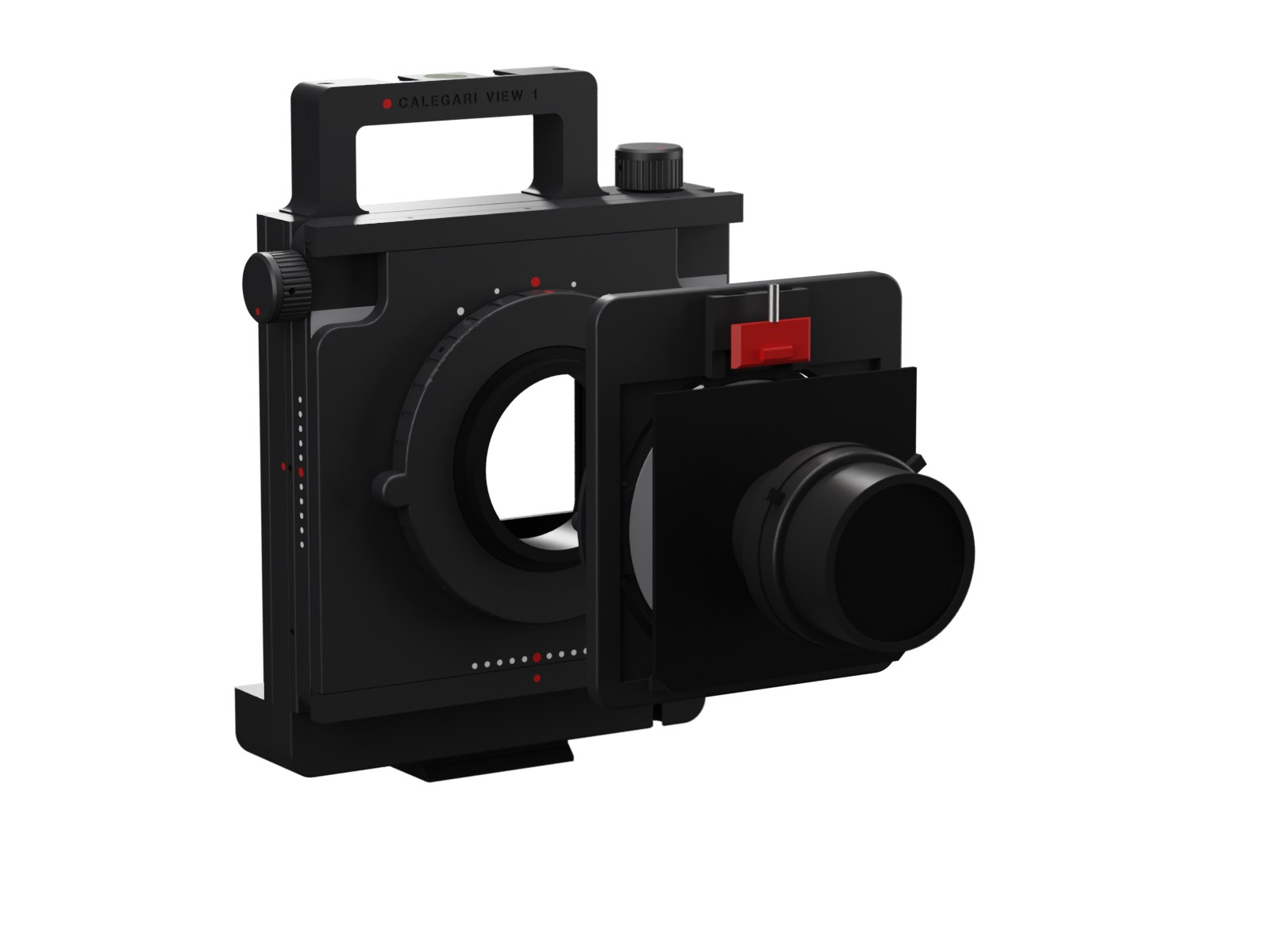
Adapter ring, two felt rings, spring latch, Technika board. Lenses change in ten seconds.
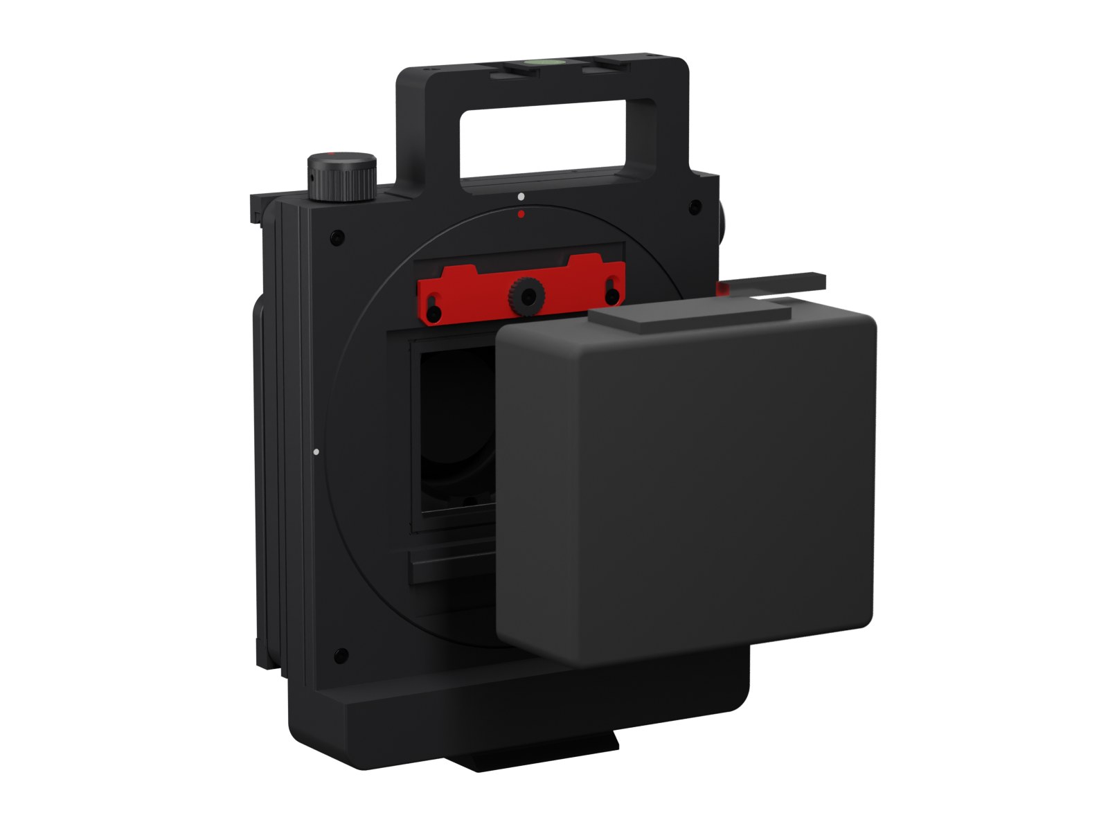
Hook under the rail, swing in, slide the blade up, tighten.
Checked before it is printed
The whole camera is a parametric model, and every change to it runs through the same checks: moving parts at every shift position, every screw against the bottom of its hole, the velvet seal between the plates, a ray trace from the lens to the corners of the film, the tripod clamp, the back in both orientations, and how each part prints. Three rounds of independent review came before the first print.
interferences among 145 parts, at home and at the four shift extremes, locks open and closed, back in landscape and portrait
narrowest velvet seal between sliding plates, at any shift
solid per printed part: no floating islands in any file
of rise or shift with clean corners at f/8 and f/22, at infinity, in both orientations; 19 + 19 combined
What a computer cannot prove, a test print can: the back interface, the dovetail fit and the M65 thread come first, on small plates, before the body. The calibration guide says what to measure and how.
Files